Current filter wheel configuration
CAIN-III has been decommissioned on Jan 1, 2019.
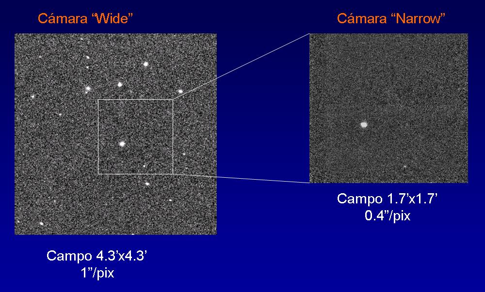
CAIN-III is a powerful and versatile instrument designed and built by the IAC. Its detector is composed by a mosaic of 256 x 256 HgCdTe photovoltaic elements (NICMOS 3 technology), sensitive in the 1.0 \u2013 2.5 µm, together with four bias electronic devices each of them controlling a quadrant and with an independent readout. Each pixel\u2019s physical size is 40 µm, corresponding to scales in the focal plane of 1 arcsec/pixel and 0.39 arcsec/pixel for the \u2018wide\u2019 and \u2018narrow\u2019 field configurations, respectively. Therefore, the field of view for these two configurations is 4.2×4.2 arcmin (wide) and 1.7×1.7 arcmin (narrow).
CAIN\u2013III is the migration of the user\u2019s software of the Infrared Camera to Linux (Fedora Core 6). This migration has involved changing the windowing system from Sun OpenWindows (OpenLook) for Motif (OpenMotif) and the data bus (former controller of San Diego) for a Linux-compatible bus (PCI bus). Cain-III maintains the same functionality as its predecessor, except for some enhancements.
The Detector
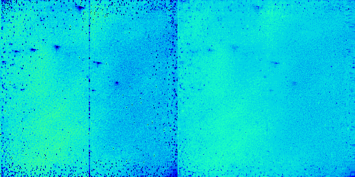
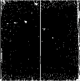
CAIN III now has a new detector, with better instrumental response and linearity. It consists of a mosaic of photoelectric elements 256 x 256 HgCdTe (NICMOS technology 3), sensitive in the 1-2.5 micron range, with four electronic bias and independent reading, each controlling a quadrant. The following Figure below shows a flat-field image taken with the new detector, which was installed in June 2008. The resulting mask is shown at the right. A total of 3127 bad pixels are located. This accounts for 4.77% of the CAIN detector.
|
Figure1: Flat field image taken with the detector CAIN-3 (left) and cosmetics, hot and dark pixels, (right) |
The detector CAIN-3 has defective pixels (hot pixels or pixels with very low sensitivity to light) which show a different signal than the rest of the detector). Figure above (right) shows a map of these pixels. However, you can easily fix those pixels by interpolation processes that implement the CAIN images reduction routines developed in the IAC. On the other hand, since dithering is typically used during the infrared observations, thie effect of the bad pixels is reduced in the final image obtained after combining several exposures.
|
|
An effect to be taken into account is the persistence, i.e., the portion of the signal that remains in the detector due to the sources observed in previous exposures. This effect consists of a non-efficient reset that appears when extremely bright stars are observed. These latent charges can be flushed by multiple resets. In this case, the detector is resetted twice before each exposure and the persistence after that remains below 1.5%.
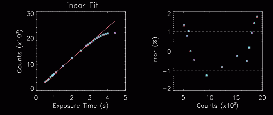
When observing in FOWLER (8-2) mode, i.e., the standard mode, the new detector is linear up 99% to 20,000 counts (se figure below).
|
The figure shows the mean value for the dome flat images taken on July 11th, 2010. The images were taken on the standard mode (FOWLER, 8,2) for a fit flat-light intensity and for varying integration times. The images were corrected of dark and bright pixels using this mask: mascara_rd.fits. The statistic of the images was calculated independently for each image quadrant. The detector linearity is now worst than in a previous test, since it behaves linear within the 2% between 4000 and 19000 counts. The same result is obtained for the four quadrants of the detector. The statistic of the images was calculated independently for each image quadrant. The detector linearity is now worst than in a previous test, since it behaves linear within the 2% between 4000 and 19000 counts. The same result is obtained for the four quadrants of the detector. |
-
Limiting Magnitude
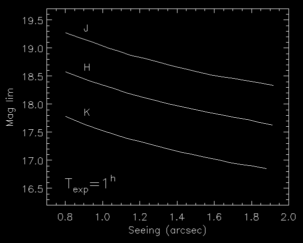
3 deep images (1 hour exposure time) in the J, H and K bands were obtained on July 3rd 2007 (R. Barrena). Seeing was 1.6 arcsec. From these images we calculated the following limiting magnitudes:
Jlim = 18.5
Hlim=17.8
Klim~17.1
- Sky magnitudes in J,H and K
We measured the sky brightness in both full and new Moon nights. (R. Barrena). Then, to maintain the sky brightness bellow 6000-8000 counts, we estimated the maximum exposure times for the three bands:
| J | H | K | |
| Dark | 15.1 | 13.2 | 11.7 |
| Bright | 14.2 | 12.7 | 11.5 |
Then, to maintain the sky brightness bellow 6000-8000 counts, we estimated the maximum exposure times for the three bands (this values are just an approximation). In narrow bands (Brg, H2(1-0), FeII, …), exposure times can be as longer as 60 s even in the `Wide’ configuration.
| J | H | K | |
| Wide | 10s | 6s | 2s |
| Narrow | 60s | 30s | 12s |
- In the table bellow we show the focus offsets with respect to the J-band focus.
| Band | Filter# | Wide | Narrow |
| J | 1 | 0 | 0 |
| H | 2 | -230 | -40 |
| K | 3 | -270 | -90 |
| Ks | 4 | -300 | 0 |
| Brg | 11 | -90 | 0 |
| Paschen Beta | 0 | 0 | |
| H2_1-0 | 9 | -50 | 0 |
| H2_2-1 | -75 | 0 | |
| Kc | 5 | -50 | 0 |
| FeII | -50 | 0 | |
| CO | 0 | 0 | |
| F5_Kc | -120 | 0 |
(last modified: august 2012)
- TCS drift, Test with CAIN
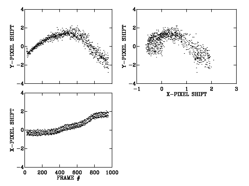
During the night 28 May, 2011 several objects were observed with CAIN from east to west overnight, The self-guided was set on and the object passed at just 3 degrees from the zenith. The following figure shows the evolution of the centroid of the object during the observations. Given the camera orientation, X is the EW direction and Y the NS direction. The displacements shown indicate the relative movement from the camera CAIN to the guiding camera FOVIA.
Results:
-
In DEC, the centroid does an almost “parabolic” movement. Between frame 500 and 700, when the object passes the meridian, the centroid is at its maximum separation from the original position. This shows how the torque of the telescope is minimal when the telescope points to the zenith and a maximum when the telescope points down, either east or west.
-
In RA, the centroid is distancing itself more than in the original position but in this case continuously. The similarity between dispersions of points in X and Y indicates that telescope tracking is similar in RA and in DEC.
-
The drift of TCS can be up to 4 pixels in DEC and 2 pixels in RA in 6 hours of observation with self-guided.
Data Reduction
José A. Acosta Pulido and Rafael Barrena, from the IAC, have developed a package of task devoted to make easy the reduction process, taking into account CAIN special features and image format. The reduction package is called CAINDR (acronym of CAIN Data Reduction). To get a copy and install the package, please contact to ttnn_a ‘at’ iac.es. Here you can read the user’s guide (only in spanish)
This new facility was made possible by the joint efforts of the student Carlos Díaz Baso and the IAC support astronomers team, and based on the IRAF package caindr. The pipeline is installed in the PC \u2018cela\u2019, at the TCS control room. To run the pipeline, follow these steps:
- Login into \u2018cela\u2019 with user \u2018obstcs2\u2019 and the password labeled on the computer.
- Go to /scratch/CAIN/pipeline and type in a terminal:
> python cain.py [directory] [option]
Where:
[directory] is the name of the observed night as is created in \u2018cir\u2019, with format \u2018ddmmmyy\u2019 (day, month, year, for example, \u201801sep13\u2019 for the images of September 1st 2013.)
[option] can be \u2018y\u2019 when the files which belong to the same observing cycle have been called with the suffix a, b,c,d\u2026 (field \u2018object\u2019). This is the preferred option and we recommend write the observing macros using this standard whenever possible. Here we show an example of macro. Otherwise, in the general case, option is \u2018n\u2019.
For example, to reduce the images taken on of September 1st 2013, we have to type:
>python cain.py 01sep13 y
The raw images are stored in /scratch/CAIN/raw_images/[directory]
The reduced images are stored in: /scratch/CAIN/red_images/[directory]
Here we find the following subdirectories:
Final_Flats, with the final \u2018flat field\u2019 iamges used in the reduction
Clean_Images, with the reduced imaged (flat and bad pixels corrected and sky subtracted). These files have the sbf.
Final_Images, with the final images which result from the combination of the \u2018n\u2019 cubes of each observing cycle within the same dithering pattern.
Furthermore, the following files are generated:
all.log, the file with all the processed images.
Imgerror.log, the file to which the server will log any errors it encounters.
Errorfind.log, the file to which the server log the images which could not be combined. We notice that, by the features of the detector and the particularities of the observations, (1 arcsec pixel size, a large amount of bad pixels, tacking problems\u2026) this combination is a complex process, not always possible to automate.
In case of problems and questions please contact to ttnn_a ‘at’ iac.es or czurita ‘at’ iac.es.
Manuals
I. Fast guide
II. Detailed Manual
Old Manuals:
User’s manual 2009
User’s manual 2010

