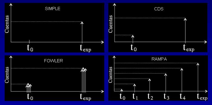
The CAIN-III NICMOS3 infrared detector, with the SDSU readout electronics, has four readout modes. They are explained below.
First of all, we adopt the following definitions in hierarchical order:
First of all, we adopt the following definitions in hierarchical order:
- FRAME: Individual array readout (equivalent to READ).
- IMAGE: Result of processing one or several frames.
- CYCLE: group of images.
- EXPOSURE: group of cycles.
The final exposure is the astronomical result so an individual FITS data file corresponds to a single exposure.
The readout modes are the following:
- SIMPLE, or Reset-Read (RR).
- FOWLER, or MRA (Multiple Readout Array) or also MNDR (Multiple Non Destructive Readout).
- CORRELATED, or CDS (Correlated Double Sampling) or also Reset-Read-Read (RRR).
- RAMP, or Non Destrictive Readout or RMP.
The figure below schematizes the different readout modes.

SIMPLE
The Simple mode performs an individual read of the array after the reset. This is the fastest readout mode.
This mode was not available in the original code. For convenience the integration time has been fixed to 50ms, exactly the readout time of a single frame and so the minimum time for an exposure.
The detector is reseted twice following the indications described in section describing detector characteristics. Therefore a simple readout mode cycle lasts:
2x50ms_reset + 1x50ms_read = 150ms (6,6 ciclos/segundo)

Figure: Simple readout mode schema. Top: RST clock; Bottom: PIXEL clock. Texp = 50ms.
- Texp = 50ms (fixed)
- SAVE: all the images.
- PROCESSING: none.
- DISPLAY: all the images.
FOWLER
The array is read out N times, the first N/2 just after the reset and the remaining N/2 after the exposure time, at the end of the integration. The final image is obtained by adding both groups of readouts and then substracting the results. It is the standard SDSU controler readout mode using the comand MRA with N/2 as argument. N must be then an even number.
The array is reseted twice and a short delay is applied at the begginig of the cycle. The command SET indicates the time between the end of the first readouts and the beggining of the second ones to the SDSU controller. That is:
SETms = TEXPms – (N/2) x 50ms
The maximum N is fixed to 64 readouts (32+32) in order to save RAM.

Figure: Fowler readout diagram. Top, RST clock; bottom, PIXEL clock. This example shows 4 readouts(2+2) and SET=200ms, so Texp=300ms. Short_delay=50ms.
- T_exp: to be determined by the user but the minimum time is (N/2)x50ms.
- SAVE: two options available, (a) (A2-A1)/(N/2) or (b) A1/(N/2) and A2/(N/2).
- PROCESSING: acumulate_1, acumulate_2, (acumulate_2-acumulate_1)/(N/2).
- DISPLAY: (acumulacte_2 – acumulate_1) / (N/2).
CORRELATED (CDS)
The array is read out twice, a first one just after the reset and the second after the exposure time, at the end of the integration. The second readout is subtracted from the first one to give the data values for that exposure. By doing this substraction, the reset noise (‘kTC noise’) is reduced. It uses the command MRA with 1 as argument. This mode is a particular case of the fowler mode.
Again, the array is reseted twice at the begining of a cycle and a short delay is applied. By default it is setted to 50ms. Each correlated cycle has the following length:
2x50ms_reset + 50ms_shortdelay + 2x50ms_read + SET= 250ms mínimo (4 ciclos/segundo)
where SET is the time between both readouts of the SDSU controller:
SETms = TEXPms – 50ms

Figure: “MRA(1)” command, or RRR readout. Top, RST clock; bottom, PIXEL clock. In this case Texp=250ms where SET=200ms. Short_delay=50ms.
- T_exp: to be determined by the user but the minimum time is 50ms.
- SAVE: two options available (a) R2-R1 or (b) both R1 y R2.
- PROCESSING: (Read_2 – Read _1).
- DISPLAY: (Read_2 – Read _1).
RAMP
It is the result of N non-destructive readout of the the array N over the total exposure time, taken at regular intervals. The resulting image is the slope obtained by a least-squares linear regression fit through the different readouts. It uses the command RMP with N as argument, where N is the number of readouts or points in the ramp. This mode was not available in the controller original code.
As in previous modes, the array is first reseted twice and a short delay is also applied. The command SET indicates to the SDSU controller the time between the end of a readout and the begining of the next one. That is:
SETms = [ TEXPms / (N-1) ] – 50ms
The maximum N is fixed to 64 in order to save RAM. Its minimum value is 2.

Figure: command “RMP(4)”diagram, or Ramp readout. Top, RST clock; bottom, PIXEL clock. This example shows 4 readouts and SET=200ms, so Texp=750ms. Short_delay=50ms
The parameters of this mode are:
- T_exp: o be determined by the user but the minimum time is 50ms.
- SAVE: All the ramp points.
- PROCESSING: none on-line.
- DISPLAY: (Last_readout – First_readout)
