Current Filter Wheel Configuration
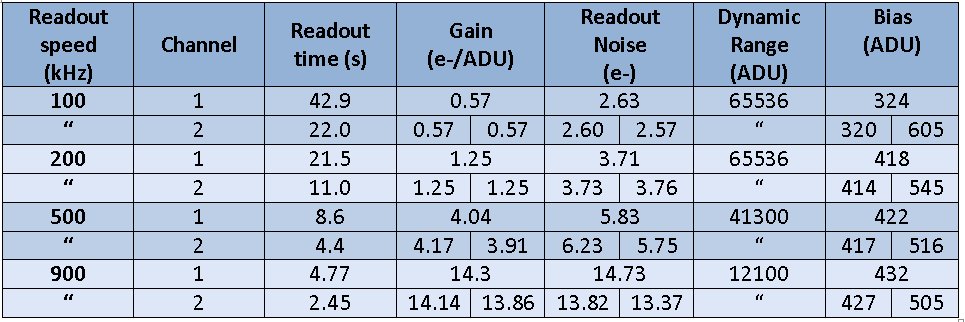
The detector is a E2V Technologies CCD42-40 back illuminated device.Two low noise amplifiers in the readout register, one at each end (channels A and B), are available for individual (A) or simultaneous (A+B) use. The detector has selectable readout (100, 200,500 or 900 kHz) to optimize for low noise or high speed operation.The 200 kHz readout frequency is the recommended. Windowing and 1×2, 2×1 or 2×2 binning are possible although, then, one single amplifier is using during the readout and there is no saving in readout time (unless a small enough window is defined).
From 2009 we are publishing the CAMELOT data at the Virtual Observatory service. These images, already reduced and astrometrized, are now available to the general user. Requests can be done using the standard VO tools, as Aladin or Topcat, or using our own Server Query Form.
Physical characteristics
-
Pixel size: 13.5×13.5 µm (0.304×0.304 arcsec)
-
Size: 2148×2048 pix (10.4×10.4 arcmin)
-
Size of useful imaging area: 2048×2048
-
Number of output amplifiers: 2
- Useful imaging area: [51:2098, 1:2048]
- Quantum Efficiency
Operational characteristics: NEW
Last characterization: 11/02/2013

Linearity:
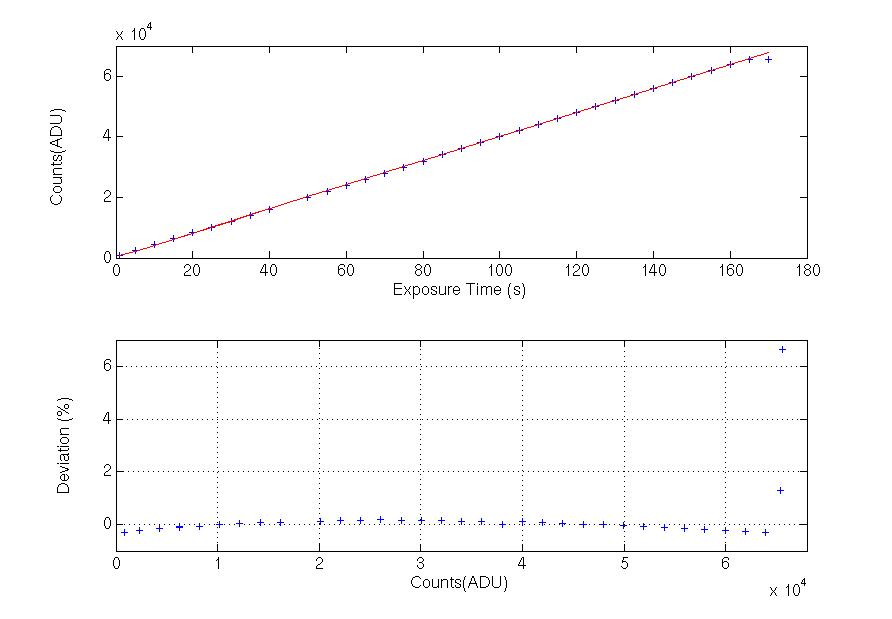
Below we show the linearity curve and the residuals after a linear fit to the central values. Residuals have an oscilation of ±0.25%. Detector is linear to 60000 counts within this limit.

Bias (February 2008)
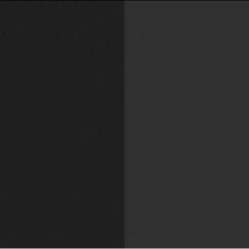
Below we show a bias frame obtained using the two readout channels and 200kHz readout frequency.
LEFT: Median 485 ADUs. RIGHT: Median 512 ADUs

NOTE: Due to problems with the electronics in the two channels readout mode, it is strongly recommended to take frames in the 1 channel readout mode.
Dome Flats
- Flat images should have between 20000 and 30000 counts in order to assure the linear response of the camera.
- We recommend to turn on the dome lights 5 minutes before starting the exposures to stabilize the lamps. Do not use the fluorescent lights.
- The exposure times here indicated are only for guidance and they could change depending on the conditions of the night.
- Under no circumstances the exposure times should be less than 5 seconds to avoid shutter effects.
-
(February 2013): Normalized dome Flats for downloading:
Jonhson-Bessel:
Sloan:
| Filters |
Lighting
|
Exposure times |
||
| Focus | Red | White | ||
| U | Pos. 7 | max | max | 145” * |
| B | Pos. 7 | off | off | 13” |
| V | Pos. 4 | off | off | 11” |
| R | Pos. 1 | off | off | 6” |
| I | off | marca – | off | 5” |
| OPEN | off | off | marca – | 5” |
| SDSS g | Pos. 5 | off | off | 10” |
| SDSS r | Pos. 1 | off | off | 6” |
| SDSS i | off | marca – | off | 7” |
| SDSS z | off | marca – | off | 10” |
| OIII #6 | Pos. 7 | max | max | 90” |
| NII #41 | Pos. 7 | max | max | 65” |
| SII #32 | Pos. 7 | max | max | 60” |
| SII #34 | Pos. 7 | max | max | 60” |
| H alpha[NII] #20 | Pos. 7 | max | 12” | |
| H alpha c #27 | Pos. 7 | max | 20” | |
| H alpha #30 | Pos. 7 | off | off | 8” |
| Hß w #63 | Pos. 7 | max | max | 40” |
| Hß n #10 | Pos. 7 | max | max | 150” * |
| Hß c #5 | Pos. 7 | max | max | 120” |
*Note: For this filters we strongly recommend taking sky flats.
Calibration
CAMELOT. Zero point offsets, extinction coefficients and color terms
Based on observation of the fields RU 149, PG0942, PG1047 and PG1525 at air masses between air masses 1,0 and 2,1.
Sloan Filters: ugriz
Below we show the zero point magnitude offsets (1), extintion coefficients (2) and color terms (3) obtained from the fits in each filter. We used the IRAF package photcal . The output file containing the fitted parameter values for each calibration equation is very useful to transform the instrumental into calibrated SDSS magnitudes using the IRAF task invertfit (the IRAF task phot was running using zmag=25).
Ajuste: u+u1+u2*Xu+u3*ug
| u1= 4.63 (+-0.07), u2= 0.46(+-0.04), u3=-0.10(+-0.02) |
Ajuste: g+b1+b2*Xg+b3*gr
| b1= 1.61 (+-0.02), b2= 0.15 (+-0.02), b3=-0.06 (+-0.01) |
Ajuste: r+v1+v2*Xr+v3*gr
| v1= 1.50 (+-0.02), v2= 0.10 (+-0.01), v3= 0.05 (+-0.01) |
Ajuste: i+r1+r2*Xi+r3*ri
| r1= 2.13 (+-0.03), r2= 0.06(+-0.02), r3= 0.03 (+-0.03) |
Ajuste: z+i1+i2*Xz+i3*rz
| i1= 3.44 (+-0.04), i2= 0.03(+-0.03), i3= 0.001 (+-0.03) |
Johnson-Bessel Filters: UBVRI
This file contains the fitted parameter values for each calibration equation to transform the instrumental into calibrated magnitudes using the IRAF task invertfit (the IRAF task phot was running using zmag=25). The zero point magnitude offsets (1), extintion coefficients (2) and color terms (3) are:
Ajuste: U+u1+u2*XU+u3*UB
| u1= 4.89 (+-0.06), u2= 0.40(+-0.04), u3=-0.22 (+-0.02) |
Ajuste: B+b1+b2*XB+b3*BV
| b1= 2.25 (+-0.03), b2= 0.16 (+-0.02), b3=-0.11 (+-0.02) |
Ajuste: V+v1+v2*XV+v3*VR
| v1= 2.00 (+-0.02), v2= 0.11 (+-0.01), v3= 0.043 (+-0.007) |
Ajuste: R+r1+r2*XR+r3*VR
| r1= 2.11 (+-0.02), r2= 0.07(+-0.01), r3= 0.16 (+-0.01) |
Ajuste: I+i1+i2*XI+i3*VI
| i1= 2.63 (+-0.03), i2= 0.04 (+-0.02), i3=-0.11 (+-0.01) |
2010 September 9th: We observed the fields PG0220, PG2213, PG2331, SA109 y SA113 at air masses between 1,0 and 1,9.
Below we show the zero point magnitude offsets (1), extintion coefficients (2) and color terms (3) obtained from the fits in each filter. We used the IRAF package photcal . The output file fitparam.dat, containing the fitted parameter values for each calibration equation, is very useful to transform an the instrumental into calibrated magnitudes using the IRAF task invertfit (the IRAF task phot was running using zmag=25).
Fit: U+u1+u2*XU+u3*UB
| u1= 4.551 (+-0.018), u2= 0.557 (+-0.014), u3=-0.234 (+-0.006) |
Fit: B+b1+b2*XB+b3*BV
| b1= 2.105 (+-0.007), b2= 0.250 (+-0.004), b3=-0.131 (+-0.004) |
Fit: V+v1+v2*XV+v3*VR
| v1= 1.969 (+-0.006), v2= 0.158 (+-0.004), v3= 0.016 (+-0.003) |
Fit: R+r1+r2*XR+r3*VR
| r1= 1.946 (+-0.005), r2= 0.108 (+-0.003), r3= 0.119 (+-0.007) |
Fit: I+i1+i2*XI+i3*VI
| i1= 2.670 (+-0.007), i2= 0.072 (+-0.004), i3=-0.006 (+-0.006) |
Pipeline
Instructions for automatic reduction (bias substraction and flat-field correction)
EThe python script ‘redcam.py’ in ‘asteroide’ (the linux PC at the IAC80 control room) automatically reduces (i.e. substracts bias and corrects flat)l the CAMELOT images. To run the macro just type in the directory iac80ccd:
>python redcam.py directorio speed channel bin
Reduced images will be stored in the scratch disc of ‘asteroide’ in the following direction:
/scratch/iac80ccd/10may02/REDUCED_200_1_11
Pixel Size
We observed different fields to determine the CCD pixel size: a field near the Galactic Plane (03 59 30, +50 57 47) in November 2005 (by R. Barrena) and M51 and M3 (by the Support Astronomer Group) in 2007 April.
The pixel size was slightly different than the theoretical value (0.333 arcsec/pix) although it does not differ from one field to the other. The transformation from pixels to celestial coordinates was made using a plate solution obtained with the perl task sextractor and the IRAF tasks ccxymatch and ccmap. Below we show the pixel size and the image rotation angle:
Coordinate mapping parameters
Sky projection geometry: tan
Reference point: 13:29:47.912 46:59:14.63 (hours degrees)
Ra/Dec logical image axes: 1 2
Reference point: 737.812 975.005 (pixels pixels)
X and Y scale: 0.304 0.304 (arcsec/pixel arcsec/pixel)
X and Y coordinate rotation: 0.040 0.053 (degrees degrees)
The output of the ccmap task is this page.
Detector Characterization lUser’s Manual Frequently Asked Questions (F.A.Q.)
