Starting on CAIN-III
Turning on
The Graphical interface
Observing with CAIN-III
MACROS
Standard Stars for CAIN-III
Observing Logs
End of observations
Turning on CAIN-III
(where dd is the day, mmm represents the moth and aa is the year; eg. on 4th June 2009 this directory is 04jun09)
To open the control interface go to the working directory in a X-terminal and write:
/scratch/cir/ddmmmaa> iac username
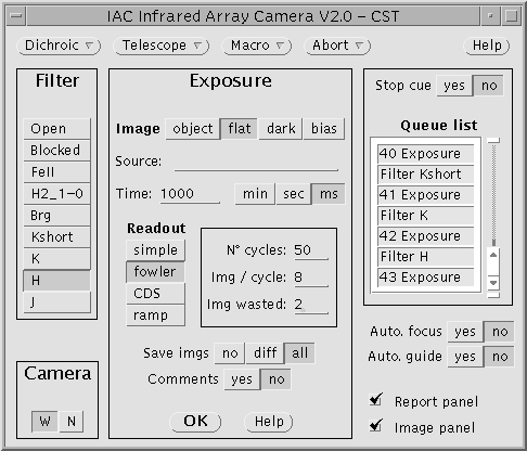
Control Panel
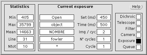
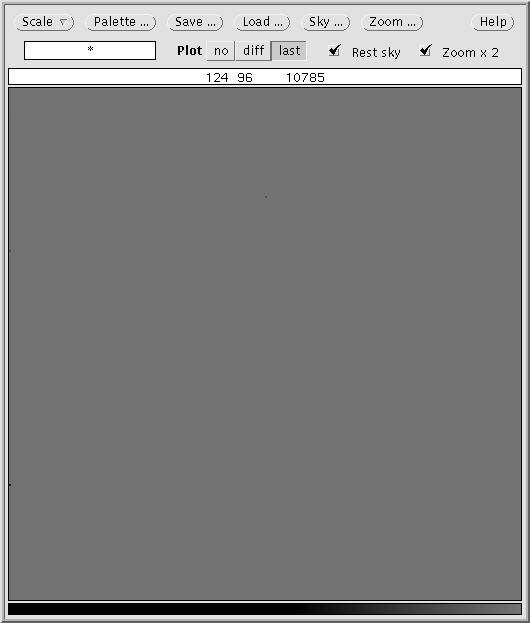
Information Panel Display Panel
The total disk space is 145 Gb. The names of all the files obtained in the same observing night have the same root formed by 7 characters indicating the date as follows: ddmmmaa_nnn (where dd is the day, mmm represents the moth, aa is the year and nnn is a counter). The file names have also extensions indicating the file type: extension log for the log, extension err for the error messages and extension fit for the image files. (See the Output files section for more information)
The graphical interface
The graphical interface consists of three working windows showed above.
All the options or menus with options can be selected by clicking on the different buttons. In some cases the menus are displayed as popup windows. Although the actions are self explained some help can be obtained by clicking on the help buttons.
Control Panel

Menus
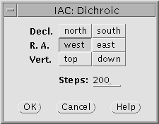

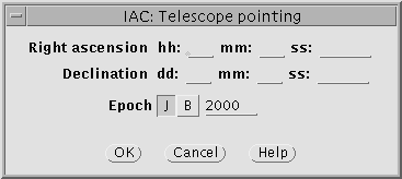
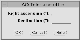
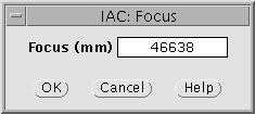
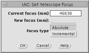
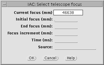
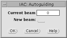
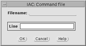
![]() Clicking on this button the user can get information about the related window.
Clicking on this button the user can get information about the related window.
Regions

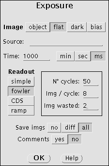
From this region in the control panel the observer can select the optical configuration. CAIN has two optical configurations: ‘wide’ and ‘narrow’. ‘Wide’ configuration has 4′.2×4′.2 field of view while ‘narrow’ field of view is 1′.7×1′.7. Pixel size is 1” and 0.”39 for ‘wide’ and ‘narrow’ configurations respectively. See the Technical Data section for details.
- The buttons on the top permit the observer to select the image type: object, flat, dark and bias. These buttons set the image type parameters correctly in the header such that objects, flats… are easy to find in the observation archives.
- From the following field in the panel the observer can put a title (Source:__) in the image header.
- Next, the exposure time in minutes, seconds or miliseconds, can be selected.
- The observer can also select the readout mode (Simple, Fowler, CDS y Ramp ).
- Depending on the current readout mode, the user can select the number of cycles, images per cycle and rejected images.
- Finally, the observer can decide to save all the images, save the final subtracted images or instead create a temporal glance image.
- User can also add a comment, even on fly (while exposing or reading out).
Information about readout modes and available exposure times can be found in the Technical data section.
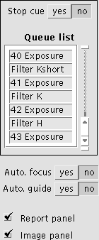
- Statistics:
- Current exposure:
- Process:


- no: none of the images will be displayed.
- diff: to show the result of the subtraction in Fowler or CDS modes and the single image or the ramp in Simple or Ramp modes.
- last: to show the last image in Fowler and CDS mode and the ramp in Ramp mode.
Taking Flats
The flat-field calibration image is necessary to correct for the varying efficiency of the individual pixels. Unlike optical bands, the heat radiation of the telescope, optic, cryostat and surrounding dome is important and has to be corrected. It is hence recommended to take flats with different levels of illumination: high and low illumination flats.
Our experience with CAIN has shown that sky and dome flats show no significant differences at the 3% level (FWHM of the gaussian histogram corresponding to the division between dome and sky flats). In any case, we recommend to take at least 50 flats in J and H band and 100 flats in K and K-short in order to decrease the noise. To take flats the option ‘image’ should be flat to set the image type parameters correctly in the header such that flats are easy to find in the observation archives.

Sky Flats.
The evening and morning twilight sky can be used to take high illumination flat field frames. The telescope should be pointed to the East or to the Zenith and opened to the twilight sky. Then, a series of exposures should be made through each filter that will be used for observing in the following order: CO, Br, K continuum, K short, K, H and J or in the reverse order (during the morning). Exposure times should be estimated to get aroud 15000-17000 counts.
Low illumination flat fields requires the same exposure time but dark sky. The difference of the two during the reduction process will give a flatfield free of telescope thermal emission. Something is wrong if we get the same counts in both high and low illumination flats! The telescope and dome thermal emission changes with time so both series of flats should be made as faster as possible. During the morning low illumination flats should be made firstly.
Dome Flats (RECOMMENDED).
Dome flats are acquired by aiming the telescope to an illuminated zone in the dome. We recommend to use the light regulated red lamps at low intensity. The exposure time should be then selected to get about 14000-15000 counts. Low illumination flat fields requires the same exposure time but no light into the dome.
Note that the heat radiation of the telescope and surrounding dome is high so, with the same exposure time and illumination, it is expected get more counts during the evening (when telescope and dome are hot) than during the morning. For this reason, there is not a standard procedure to take infrared dome flats. In any case we recommend about 15000 counts and less than 4000 counts for high and low illumination flats respectively.
Why are low illumination flats necessary? Flats are more complicated in the infrared, because every frame we take, including flat field frames, have an additive extra component arising from the radiation coming from the telescope and dome structures. This is more of a problem at longer IR wavelengths, because at shorter ones, the sky dominates. For this reason we take dome flats with and without lights (or twilight and dark sky flats) and subtract the two to create the final flat frame.
IMPORTANT: Our experience has shown that the thermal contribution in the J and H band is not high so with these filters low illumination flats are not necessary.
Taking Bias and Darks
¿Do we need to take Bias?
Users interested in photometric precision should take many bias with different exposure times. The bias of CAIN-III has a significant drift, that can reacht 1200 negative counts in 10 seconds. That is, if you take a bias (Blocked filter) with CDS Texp = 1s and Iw = 2 is flat, but with a diff value of -300. With 2s you get -600, with 5s get -1000 and with 10s get -1050/-1100, and stay there.
This effect is rather exponential, so to properly subtract the bias is necessary to have bias with exactly the same exposure time that the image you want to subtract the bias. This drop occurs in the time between the two readouts, so it has no sense to think that by subtracting the second from the first, which is what is usually done when processing images FOWLER, the bias is removed.
Therefore, the bias is only required if the user uses the readout modes SIMPLE and RAMP
How can we take Bias?
Infrared detectors have not shutter so we can consider that a bias frame is equivalent to a simple readout mode image taken with the shortest possible exposure time (50 ms in CAIN) and no illumination at all (closing the dome and mirror covers and placing the blocked filter). To take bias the option ‘image’ should be bias to set the image type parameters correctly in the header such that bias are easy to find in the observation archives.
- Step 1. Place the Blocked filter
- Step 2. Select Image: bias
DARKS
Secondary-Dichroic Alignement
This procedure is responsability of the support astronomers.
Focusing
2) Display the image in IRAF and use “imexam” in to see how bright the stars in the field are; figure out good exposure time for them.
3) Take an exposure with the J filter. Note that all the filters and camera options have an associated focus offset. If the option ‘autofocus’ is YES the focus will be automatically updated for filter and/or camera using these offsets.
4) Use “imexam” -r to check the profile (measuring FWHM) and “imexam”-e to check the star contours. Note that the pixel size is 1” and 0.”39 arcsec for the Wide and Narrow configurations respectively.
5) Move telescope focus (in the telescope control computer) and repeat steps 3-5 until you get a reasonably good shape and width for the observed PSFs.

Problems
Basic observing procedure
Observing in the infrared is more complicated than in the optical domain. On one hand, absorption by the atmosphere is significant (see figure below) and, on the other hand, the atmosphere itself radiates strongly with the sky background emission being variable in a timescale of minutes.
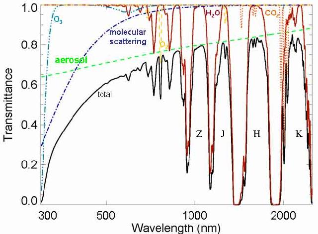
So, from ground based telescopes we can only observe at the infrared wavelengths which can pass through the Earth’s atmosphere and at which the atmosphere is dim. The near-infrared JHK photometric filters are designed to transmit in these “windows”. In any case, the radiation from the atmosphere itself varies with timescales of minutes.
For all these reasons it is very important to devise an observation strategy that accounts for these peculiarities and that provides a precise way of estimating and subtracting the background. Basically the way of obtaining an accurate sky subtraction is observing the target followed by an external sky observation. It is a complex optimization problem that has to takes into account the size of the target: small targets (or uncrowded fields) require different strategy than large targets (or crowded fields).
About flat-field calibration images, unlike optical bands, the heat radiation of the telescope, optic, cryostat and surrounding dome is important and has to be corrected. It is hence recommended to take flats with different levels of illumination (high and low illumination flats) and subtract the two to create the final flat frame.
To help the observer we present a guideline of possible observing strategies:
Point Sources
If the targets are very small compared to the size of the detector, or if the crowding is such that most of the detector is actually occupied by blank sky, then, by jitter imaging, it is possible to use the target images themselves to estimate the sky (see example). This is achieved by combining the target images using rejection algorithms, so that the result is a blank sky image. The observer has to consider:
- A dithering pattern of 4 positions at the most can be created using the facilities of the autoguider FOVIA. This is an example of macro to do so.
- To create a dithering pattern of more than 4 positions we cannot use the autoguider system but order direct offsets to the telescope. It is important to note that the best results are achieved when a large number of positions are obtained (although in practice a 9-point jitter should be good enough). Note that the tracking at the TCS is not very good so we will have to recenter the target from time to time (every 20 minutes or so).
Extended Sources
In this case, the target images are not suitable to construct a sky image, and separate sky observations (ideally with the same exposure time) are required. The radiation from the sky varies with timescales of minutes so sky observations should be obtained immediately after (or before) target images. Below we show an example of dithering pattern for extended sources.
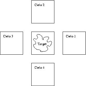
Figure 1: example of dithering pattern for extended targets. In this case we recommend the following sequence: T, C1, T, C2, T, C3, T, C4, …. (Note: Cielo=Sky)
The sky image is then obtained by combining frames C1, C2, C3 and C4. Given the time scale of variability of the background these sequences should last less 5 min in J and H and 10 min in K and K-short.
Very Bright Point Sources
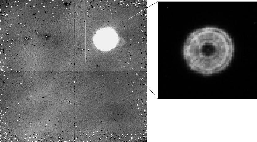
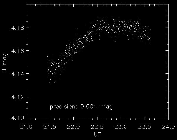
Figure below shows the light curve of a 4th magnitude non-variable star observed 3.5 hours from airmass 1 to 1.6. The exposure time was 5 seconds. The variation (0.04 magnitudes in 0.6 air masses) shows the atmospheric extinction while the dispersion (0.004 mags!) gives us the accuracy of the photometry. We performed aperture photometry to enclose the whole stellar ‘donut’ whereas the sky was estimated from an annulus around the star.
Macros
A session of observation in general comprises five actions: changing filters, changing camera, exposing, moving the dichroic and offsetting the telescope. A macro consists of a list of commands available to the observer to execute these actions. There is great flexibility when writing macros and both their syntax and format are very simple and intuitive:
- The observer can choose any name for the file, with or without extension.
- The file must contain an action per line.
- Blanks are ignored.
- Comments should be always preceded by “!”
- Capitals are undistinguished from small letters.
The syntax consists of one of the five actions above followed by a colon “:” and the desired arguments (see list of commands)
Example
Below we show a macro created for observing a galaxy. The idea is taking the target and separate sky observations (cielo) alternately. The autoguider is not activated and the telescope is moved 300 arcsec in RA for the sky positions. The target is however centered in two positions defining two beams (bs 1 and bs 2) in the guider system (FOVIA). These two beams are close enough to locate the galaxy almost in the same position although slightly different to reduce noise from the effects of bad pixels.
Telescope autoguiding : bs 1
Exposure : object NGC5350 , CDS 12 0, 10000 , all
Telescope offset: -900 0
Exposure : object cielo , CDS 12 0, 10000 , all
Telescope offset: 300 0
Exposure : object cielo , CDS 12 0, 10000 , all
Telescope offset: 600 0
Telescope autoguiding : off
Telescope autoguiding : bs 2
Exposure : object NGC5350 , CDS 12 0, 10000 , all
Telescope autoguiding : off
Telescope autoguiding : bs 1
Exposure : object NGC5350 , CDS 12 0, 10000 , all
Telescope offset: 900 0
Exposure : object cielo , CDS 12 0, 10000 , all
Telescope offset: -300 0
Exposure : object cielo , CDS 12 0, 10000 , all
Telescope offset: -600 0
Telescope autoguiding : off
Telescope autoguiding : bs 2
Exposure : object NGC5350 , CDS 12 0, 10000 , all
Telescope autoguiding : off
Complete Command list.
Macros can contain any of the following command (in alphabetic order):
Bell:
Causes the computer to generate a beep.
Camera: (Cámara)
Changes the camera between Narrow and Wide optics.
Dichroic: (direction) <steps>
Moves the dichroic (only for support astronomers)
Exposure: (Type-of-Image) (Target-Name) , (Readout-mode) <cycles> [<points>] [<#-Wasted-images>], [<Exposure-Time ms>] , (Save-the-image)
Fields between square brackets “[]” depend on the readout mode:
- Simple -> <N-series>
- Fowler -> <N-series> <N-points> <N-Wasted-images> , <Texp ms>
- CDS -> <N-series> <N-Wasted-images> , <Texp ms>
- Ramp -> <N-series> <N-points> , <Texp ms>
Takes an exposure with the following arguments: type of image (object, dark, flat or bias), target name, readout mode (simple, fowler, CDS or ramp), number of cycles, points, series, wasted images and exposure time.
Filter: (filtro)
Changes filter (Current options are: Open, Blocked, Kcont, H2_1-0, CO, Kshort, K, H o J.)
Telescope autoguiding: fov | off | bs <#-beam>
Activates/stops the guiding (FOVIA)
- fov = switch guiding on.
- off = switch guiding off.
- bs = changes beam (1, 2, 3 or 4)
Observer needs first configurate the autoguider by choosing the positions of beams in the FOVIA window.
Telescope focus: [+/-] <focus>
Telescope offset: <arc sec ra.> <arc sec dec.>
(Offset.)
Moves the telescope in RA and/or DEC the desired amount in arc sec.
Telescope pointing: <hh> <mm> <ss.> , <dd> <mm> <ss.> , B | J <year>
(Pointing.)
Points the telescope to the desired coordinates. We recommend however point the telescope from the telescope control computer.
End
Indicates the end of the macro although can be place in any position not only when the macro ends.
Brackets indicate the different arguments and should not be written in the macro file. Furthermore, all the commands can be executed by means the Control Panel (the parameter are the same) so parameters should have the same format than in this window.
- Numbers between < > are real.
- Characters between brackets “( )” indicate the same actions than options in the control panel. Only the first word is compulsory.
- Brackets “[ ]” are arguments depending on the above commands.
- Symbol “|” means “or logic”.
- Commas are necessary.
Template Macros
In the links below we show two macros than can be used as template. Observer can create his/her own macro by editing these templates with the desired parameters.
Macro 1. Performs a 4 positions dithering pattern using the 4 four beams of the autoguider. Uses the “fowler 8 2” readout mode, with 10 cycles, 5 seconds exposure time and filter K. The dithering is executed twice. 3 beeps sound when the macro ends.
Macro 2. Performs a 9 position dithering pattern by moving the telescope with the autoguider off. Uses the fowler 8 2 readout mode, with 10 cycles, 2 seconds exposure time and filter J. 3 beep sound when the macro ends.
How to execute a macro
The menu ![]() in the Control panel opens a window where the observer can write the name (with the path!) of the macro file. The macro is read and its syntax is checked when the user clicks on the “OK” button. If any error occurs the process stops, otherwise, the macro is executed.
in the Control panel opens a window where the observer can write the name (with the path!) of the macro file. The macro is read and its syntax is checked when the user clicks on the “OK” button. If any error occurs the process stops, otherwise, the macro is executed.
Standard Stars for CAIN-III
We have selected a sample of standard stars suitable for observing with the TCS and CAIN: the UKIRT faint standard stars, other standars and Arnica standard stars. A catalog with the coordinates of the UKIRT faint standards called UKIRT.USU is stored in the telescope control PC.
Observing logs (VIEWLOG)
An observing log can be obtained executing the script viewlog from ‘cir’ (the working computer). By typing viewlog_tcs in a X-term the window below appears:
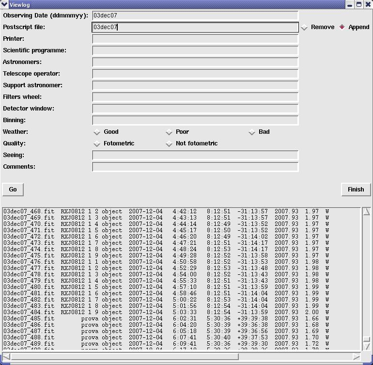
The observer has to fill the fields Observing date and Postscript file, select the command “Append” and execute the task by clicking on “Go”. All the other fields are optional. After a few seconds the window will show a list of the images with their main header parameters (UT, RA, DEC, airmass, camera, exposure time, filter, cycles, focus…).
The script will create a text and a postscript file called date.LOG and date.ps respectively.
Closing Down
After the observing night the observer has to close the control interface window.
The telescope operator will close down the telescope control PC, the autoguider (FOVIA) and all the electronic systems, however the observer has to close the mirror covers and the dome upper and lower hatches (ventana and compuerta respectively).
Data transfering
The observer can transfer his/her data by ftp by our Internet connection, copy them to an external USB disk or ask the telescope operator to save the files in a DVD. This DVD can be picked up the afternoon after the observing night. Data from CAIN is stored as standard fits.
IMPORTANT. After each observing run all the files created by the observers will be remove from our disk. CAIN-III has a system of automatic data backup that runs after finishing the observing night.
